



Custom Semi-Tubular Rivets: How to Specify Hole Depth and Grip for a First-Time-Right Order

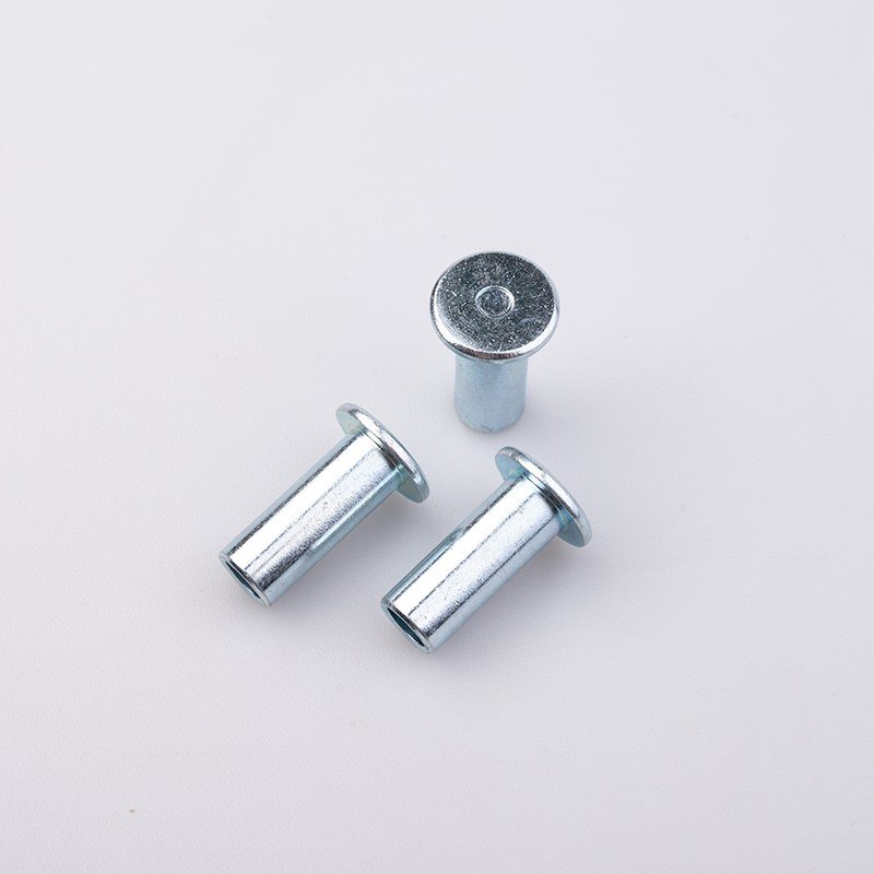
Drill a shallow blind hole into the tail of a solid rivet and you change nearly everything about how the part behaves, while changing almost nothing visible in a catalogue photograph. On a semi-tubular rivet the hole is not a feature added to the part: the hole is the part. Its depth sets the force the tool needs; the wall around it decides whether the tail rolls or tears; where the bore bottoms out, relative to the material clamped, decides whether the joint closes at all. Yet the bore is the line most often missing from the enquiries that reach us.
What the blind hole is actually doing
A rivet sets because the tail deforms. In a solid rivet that means upsetting: the tail is compressed and swells outward, and the force climbs steeply with diameter. Drill a bore and upsetting becomes rolling — the thin annular wall has somewhere to go, so it curls outward under a fraction of the load. Three consequences follow:
- Setting force drops sharply. Hand tools and light automatic riveters close joints that would otherwise need a press — decisive where the joined parts cannot take that load.
- Deformation becomes predictable. Material moves where the bore allows, so the head forms in a controlled shape instead of wherever the shank buckles.
- Shear capacity is traded away in proportion. Depth removed is section removed. A solid shank remains below the bore, so real strength survives — but the depth you specify is where you stop buying strength and start buying formability.
Hole depth, then, is the dial that sets where your part sits between a solid rivet and a tube.
Same joint, three different answers
Nearly every enquiry here is really a question about which of three types the joint needs. All three solve one problem — holding a stack with a head formed at assembly — so read across.
| Solid rivet | Semi-tubular rivet | Fully tubular rivet | |
| The hole | None; full section | Blind bore in the tail, solid shank below | Bore runs full length |
| How the tail forms | Upset and swelled outward | Thin wall rolls, body stays intact | Whole wall flares |
| Setting force | Highest; usually a press | Low; hand or light automatic tools | Lowest |
| Shear retained | Full | Reduced by bore depth, still substantial | Lowest |
| Sensitivity to grip | Moderate | Severe; grip and bore depth must agree | Severe |
| Usual assembly failure | Deforms the parts joined | Starved or folded head from wrong bore depth | Splits at the flare |
| Choose it when | Load matters more than gentleness | You need shear strength without press force | Pivot joints, or soft light-load stacks |
The middle column is a deliberate compromise: more strength than a fully tubular rivet, less force than a solid one. A compromise holds only if its terms are written down — and the terms are bore depth and grip.
Depth measured against grip, never on its own
A bore depth in isolation means nothing; what matters is where the hole ends relative to the clamped stack. End well below the joint line and the section that must roll is short and stiff, so the tool stalls or the head comes out starved. Let the bore run up inside the clamped material and the shank is hollow where it should carry shear.
Proportion works the same way. A buyer in the United States asked for a semi-tubular rivet at φ0.097″ × 0.72″ — slender for its length, so the tail must roll square across a large grip without buckling. Such geometry has no tolerance for a grip figure estimated rather than measured. An Algerian buyer needed rivets at 4.8 × 10 mm drilled from both ends, where the two depths must match so the part sets identically whichever way it feeds: a symmetric bore is the tighter requirement, not the looser.
Wall thickness, and whether the tail rolls or tears
Depth gets discussed; wall thickness rarely does, though at a given diameter the two are one geometry read twice. Too much wall and the tail resists rolling; too little and it tears.
The margin narrows as parts get smaller. An Indian buyer specified a flat-head semi-hole rivet at 2.8 × 7.5 mm, where a bore drilled slightly deep leaves almost no wall to work with. Material shifts the same balance: a separate Indian buyer ordered stainless semi-tubular rivets in several sizes, and stainless work-hardens as the tail rolls, so a wall and hardness pairing that forms cleanly in carbon steel can crack at identical geometry. Wall, material and hardness are one specification, not three.
Confirming a feature you cannot see from outside
A blind bore is invisible on a finished part, so it must be controlled in forming, then evidenced. Common diameters are cold-headed from wire on our own line at φ2.0–15.8 mm, lengths up to 140 mm — covering the metric shanks and the inch-series bodies above — with the bore formed to depth in the same operation. Heads and batches that do not justify a die are turned at φ2–200 mm.
Verification follows the same logic. Length, diameter and bore geometry are read on an optical profile projector covering 0–300 mm at ±0.0005 precision. Hardness is confirmed across HV100–800 Vickers and HRC20–70 Rockwell, evidencing formability and shear strength together. Full lots pass optical sorting reading outer diameter and length on every piece to within 0.01 mm; shear is checked on a tensile machine, and plated parts go through salt spray. Sign-off before shipment appears in pre-shipment inspection.
The lines about the hole your drawing must carry
Most of a rivet enquiry is straightforward. These lines let us quote once rather than twice:
- Bore depth, with a tolerance, and whether the hole is in one end or both — stated as a dimension, not inferred from the length.
- Grip: the total thickness clamped, so shank length matches your stack rather than being reverse-engineered from a sample.
- Shank diameter and length with tolerances, in whichever unit your drawing uses.
- Head style — flat, oval or countersunk — with the included angle if countersunk.
- Material and finish: carbon steel, stainless, aluminium or copper, plain or plated, and the environment it faces.
- A drawing or a sample. If neither exists, send the parts the rivet joins: we reverse the specification, bore included, for approval before quoting — the route in custom fasteners made to your drawing.
The same attention runs through neighbouring parts on these lines, such as connector and straight pins; the wider range sits under bolts and screws.
Send the rivet drawing, or the assembly it has to hold together. What comes back states the bore explicitly: a specification you can hold every shipment against, not a part number hiding the dimension that governs it.