
Connecting Bolts Drawn to ±0.05 mm Everywhere: Which Dimensions Actually Decide the Fit
Only three dimensions on a cam connecting bolt decide the fit with the cam. Hold those at ±0.05 mm and leave the rest at routine tolerance.

Short answer: On a cam connecting bolt, the fit with the cam depends on three things: the head diameter, the head thickness and the position of the head along the bolt. Those deserve a tight tolerance such as ±0.05 mm. If every other length, bend and chamfer carries ±0.05 mm as well, part of the drawing cannot be held at a sensible cost, and the quote comes back with exceptions.
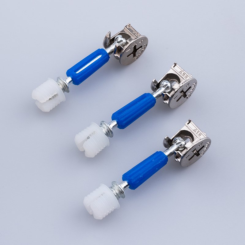
Which dimensions does the cam actually feel?
In a three-in-one connector the bolt is screwed into one panel, passes through the edge of the second panel, and ends in a cam. When the cam is turned, its eccentric track catches the head of the bolt and pulls the two panels together. Three features decide whether that works:
- Head diameter. The head has to enter the cam and still be caught by the track.
- Head thickness and the neck under it. These decide how the head sits in the slot of the cam. A difference in the region of 0.05 mm here is enough to make a joint hard to assemble, loose after tightening, or noisy.
- Head position. The distance from the shoulder at the end of the thread to the underside of the head puts the head where the cam can reach it. It has to match the panel thickness and the position of the cam bore.
Head position is easy to overlook, and its effect is easy to see. A woodworker on a German forum drilled the bore for a 15 mm cam 39 mm from the panel edge instead of the 34 mm his system called for. His cam then turned without catching anything, and he went looking for a longer bolt. The bolt was fine; its head was simply not where the cam expected it.
What ±0.05 mm on every dimension does to a quote
Tight tolerances on dimensions that do not affect the fit are the most common way buyers raise their own price without meaning to. Cost does not rise in a straight line as a tolerance narrows. Each step can mean slower settings, more checks or a second operation, and the tightest steps need grinding.
A furniture customer in New Zealand sent us drawings for a connecting bolt bent to 90° and a three-in-one connecting bolt, sized 6.5 × 45 mm and M6 × 44.5 mm. Both drawings carried ±0.05 mm on every dimension. We told the customer we could not hold all of it, marked the dimensions that matter for assembly, and sent back a drawing showing the tolerance we could hold on each feature. The design was still changing at the time, and the customer wanted grooves added to the bent bolt; at our suggestion the four grooves were placed in the middle of it.
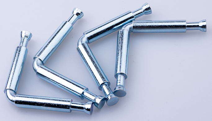
The second drawing is the part worth copying. It answers the question a quote depends on: which features have to be tight, and which can stay at a routine tolerance.
What tolerances we can hold
- Diameters up to 8 mm: ±0.1 mm or ±0.05 mm as standard, and ±0.03 mm on custom parts where the fit needs it.
- Lengths and other non-critical dimensions: our routine tolerance is ±0.3 mm up to 30 mm and ±0.5 mm above 30 mm.
If a length has to be tighter than that, head position being the usual case, mark it on the drawing and we will tell you what we can hold before we quote.
How to mark a connecting bolt drawing
- Mark the head diameter, head thickness and head position as critical, and give those the tight tolerance.
- State the panel thickness and the cam the bolt works with, for example a 15 mm cam, so the head position can be checked against the set.
- Leave the rest at routine tolerance. Before production we often suggest three edits: a 0.5 × 45° chamfer marked as not inspected, a sharp R0.2 corner left as the radius the forming tool produces, and non-critical dimensions changed to reference (Ref). The revised drawing goes back to you with English notes for approval.
If you have a connecting bolt drawing with tight tolerances throughout, send it by email to zoe@tfscrew.com together with the panel thickness and the cam it is used with. We will mark the dimensions we would hold tight and send the drawing back with the quote.
Related: what to specify for furniture connecting bolts and cam locks · custom fasteners made to your drawing
How this was written: the case comes from our inquiry records (2025–2026). The tolerance figures are our internal standard. The forum example is paraphrased from a public woodworking forum. Customer names and drawings are withheld.